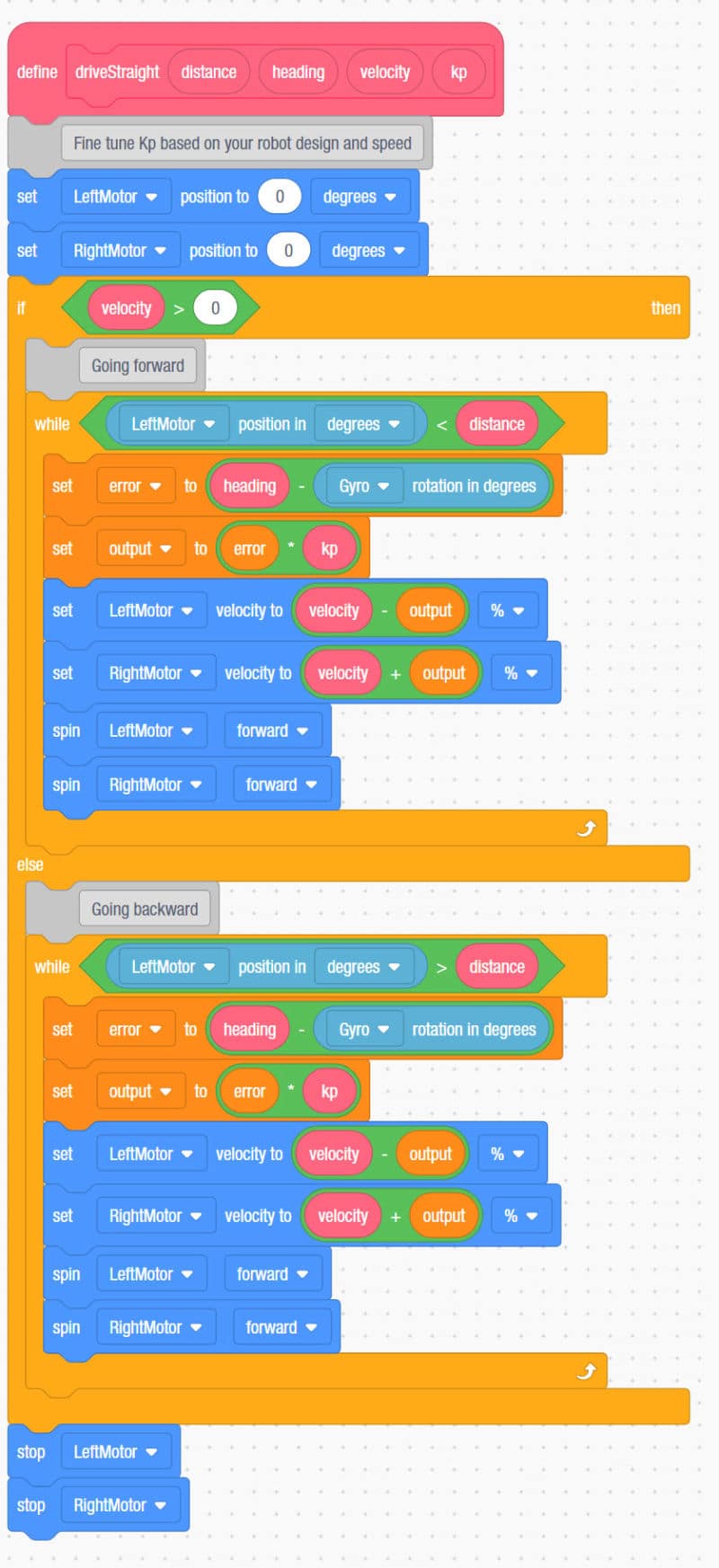

In theory this reduction in power and slowing rate of turn will eliminate the overshoot. As the turn gets closer to 90 degrees, the PID routine starts to return smaller and smaller values thus reducing the power being applied and slowing the rate of turn. As the turn progresses, the angle of turn is fed to the PID controller routine which measures error and produces a value (the turn power) at or near the starting (full) power.
#Robotc pid control full
So in our example we start out turning away from zero towards 90 degrees at the full power we specify. The idea behind a PID controller is to take the desired state value (90 degrees in our turn example), compare that to the actual (feedback) state value (the current gyro or IMU angle) and apply factors to the difference (called the error) that produce a proportional output value. PID stands for Proportional, Integral, Derivative.


#Robotc pid control software
To do this we will use a software routine called a PID controller. Fixing this can be tricky to do manually but there is an automated way to better control the turn. On our test robot, a 90 degree turn would end up being 110-120 degrees. When turning at a constant power setting and setting the power to zero when the target angle is reached, depending on motor configuration, gear ratio, robot weight and the turn power, the robot will most likely not stop quick enough to be on the desired angle. With the test robot used to develop this course, there is a problem with the previous examples of turning under gyro or IMU control.


 0 kommentar(er)
